Feature
In the Pipeline: District Energy and Green Building
While most green design strategies work at the scale of individual buildings, some of the most exciting opportunities avail themselves only when we look at the larger scale. Building for mixed uses can reduce automobile dependence, for example, and compact development can be coupled with the permanent protection of open areas. We should add to this list of macro-scale green building opportunities another: district energy systems, especially those utilizing waste heat from power generation and those using renewable energy sources.
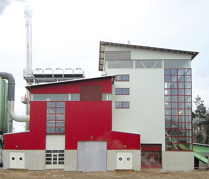
Located in Baden-Baden, Germany, this Biopower 5 CEX plant, manufactured by Wärtsilä Corporation of Finland, burns wood chips to provide 5.3 MWe of electricity and 3.5 MWth of hot water, which is distributed through a district heating system.
Photo: Wärtsiläcombined heat and power (CHP) plants—also known as
cogeneration—significantly boost the overall efficiency at which the primary energy source is converted into useful energy. District energy from a CHP plant offers even greater environmental benefits when the source energy is renewable or low-impact, as is the case with high-temperature geothermal, wood chips, or landfill gas.
This article examines district energy systems and the use of waste heat and renewable energy sources for the distributed thermal energy. As strategies for reducing the environmental impacts of buildings and achieving significant economic savings, these options have received surprisingly little attention in either the mainstream building industry or the green building community. While this article is probably most immediately relevant to those involved with larger buildings and macro-scale planning, there is also significant potential for supplying single-family homes with district energy—a practice that is common in northern Europe.
History of District Energy
District energy systems are far from new; the idea has been around for centuries, even millennia. Distributing hot water in pipes dates back to ancient Rome, when hot water was piped from bathhouses to greenhouses. Piping hot water from geothermal sources goes at least as far back as the Middle Ages. The French village Chaudes-Aigues, Cantal, has obtained its heat from hot springs continuously since the early 14th century; originally the hot water was distributed through wooden pipes.
According to the International District Energy Association (IDEA), the first district steam heating system in North America was installed at the U.S. Naval Academy in Annapolis, Maryland, in 1853. The first steam heating system to serve a downtown community was built in 1877 in Lockport, New York (near Buffalo) by hydraulic engineer Birdsill Holly, who is generally considered the father of modern district energy. Between 1877 and 1882, the Holly Steam Combination Company built nearly 50 district steam heating systems, one of which still supplies heat to downtown Denver. The successor company, American District Steam Company, installed hundreds of systems over the next 80 years.
Electric utilities became involved in district heat and CHP very early. When Thomas Edison built his first power plant in downtown Philadelphia in 1906, he determined that the venture would be profitable only if he sold the waste heat from the generator, so he entered into a contract to supply steam to nearby Thomas Jefferson University Hospital; this was the first-ever application of CHP. That district steam system is still in operation after more than 100 years.
Prior to the 1960s, the majority of urban district energy systems distributed steam from downtown CHP plants. During the 1960s and ‘70s, as utility companies began building larger coal and nuclear power plants in remote locations and closing their downtown power plants, distributing the waste heat lost favor. Steam requirements also dropped as thermal loads changed in larger commercial buildings, and internal cooling loads generated by electric lighting and then computers began to exceed heating loads.
Since the 1980s, large urban areas have seen a greater emphasis on district cooling than on district heating. These systems distribute chilled water or a slurry of ice and water that is generally produced using electricity. District cooling actually dates to the late 1800s; Denver’s Colorado Automatic Refrigerator Company began supplying chilled air to houses through pipes in 1889. Commercial-scale, chilled-water district cooling systems began operations at the Rockefeller Center in New York City and the U.S. Capitol buildings in the 1930s.
According to Danny Harvey, Ph.D., in his 2006 book,
A Handbook on Low-Energy Buildings and District-Energy Systems, there are currently about 6,000 district energy systems in North America. They include roughly 2,000 university systems, 2,000 systems serving medical facilities, and 2,000 other systems, including systems serving downtown urban areas. Such systems serve more than 10% of nonresidential floor space in the U.S., according to Harvey, and about 10% of these systems derive their heat from CHP plants. New district energy systems are coming online each year, but older systems have been disappearing. Minnesota, for example, had 40 district energy systems in the 1950s, while only a handful remain today.
Table 1. District Heat and CHP Use in Selected European Countries
Understanding District Energy
District energy systems have three basic components: a source of thermal energy, a piping network to distribute that energy, and a mechanism for utilizing that energy in buildings. These components are addressed below.Producing heat for district energy systems
Fossil Fuel Combustion. The heat source for most district energy systems is fossil fuel combustion using coal, natural gas, or oil (usually #2 or #6 heating oil). Steam or hot water can be produced in large boilers as the sole output, or this thermal energy can be a byproduct of electric power generation—a practice referred to as combined heat and power (CHP) or cogeneration. Environmentally, CHP has many advantages, as described below.
When chilled water is needed for district cooling systems, it can be produced at power plants or at satellite cooling plants that serve clusters of buildings. Electricity can be used to chill the water using large electric chillers (ideally operating at night with chilled water stored for daytime use), or a heat source can chill the water—typically using absorption cooling—so there is a wide range of options for the chilled water production.
While chilled water can be distributed directly through district cooling systems, another option is to distribute only heat and then to use that heat within buildings for cooling using thermally activated absorption chillers, adsorption chillers, or desiccant dehumidification systems. This practice can avoid the need to run dual piping loops.
Fossil Fuel CHP. Combined heat and power is an attractive option for district heating because it allows for the use of thermal energy that would otherwise be lost. In a typical coal-fired power plant today, about two-thirds of the primary energy content of the coal is lost as waste heat. Exactly how much heat is wasted depends greatly on the combustion technology used.
Conventional coal plants pulverize the coal and inject it into a furnace that produces pressurized steam; 33%–35% power generation efficiency is typical with these plants, though the latest technologies can achieve efficiencies as high as 45%. More advanced
integrated gasification combined cycle (IGCC) coal-fired power plants first gasify the coal by heating it to a very high temperature (1,800°F, 1,000°C) at high pressure in the presence of pure oxygen. The resultant gases (primarily hydrogen) are burned in a gas turbine at generation efficiencies of 42%–48%.
Natural gas is most efficiently burned in
natural gas combined cycle power plants that can achieve efficiencies of 50%–60%. Such systems are typically 25 megawatts (MW) or larger.
Microturbine gas generators operate at significantly lower efficiency (25%–29%), but their smaller size enables them to be used in buildings where the waste heat can be easily captured and used within the building.
Fuel oil is generally used in power plants of a few megawatts and smaller using
reciprocating engines—essentially large diesel engines similar to those used in heavy equipment. (Caterpillar, Inc. and Cummins, Inc., are two of the largest producers of reciprocating engine generators.) Electrical efficiency ranges from about 33% at 100-kilowatt (kW) capacity up to 41% at 5-MW capacity.
What about nuclear power? With an average generation efficiency of 30%, the large amount of waste heat generated by nuclear power plants makes them well suited to district energy systems. However, the typical isolation of nuclear power plants and concern about radioactivity has resulted in almost no district energy being derived from these plants—and none in North America.
Geothermal Heat and Deep-Lake Cooling. Where there is a convenient source of high-temperature geothermal energy, distributing this heat through district energy systems is an obvious choice. Roughly 95% of all space and water heating in Iceland is provided by geothermal district energy systems from the country’s tremendous geothermal resources. The oldest continually operating district energy system in the world (in France—see above) relies on a natural hot spring. In Boise, Idaho, a geothermal system has been heating a portion of the city since 1892, and dozens of other systems supply geothermal district heat throughout the western states. According to the Sustainable Energy Solutions Group at Northern Arizona University (www.geothermal.nau.edu), in 1998, 1,905 MW of thermal energy (MWth) were supplied through geothermal district energy systems in the U.S. and 4,645 MWth in Europe.
In most geothermal district energy systems, water is pumped underground, where it is heated, then pumped back out for distribution. In some systems, high-pressure steam is used for power generation, and the waste heat is distributed as district heat. The use of geothermal energy for district heating has been increasing in the U.S. in recent decades, but the potential is limited to geologically active areas. A new report by the Massachusetts Institute of Technology (see newsbrief, MIT Report Emphasizes Geothermal Power Potential) concludes that the geothermal resources in the U.S. that could be economically recovered are significantly greater than has long been believed.In addition to capturing underground geothermal heat, some district energy systems provide
district cooling using water from deep lakes. The City of Toronto is pumping 39°F (4°C) water from a depth of 260 feet (80 m) in Lake Ontario to cool portions of the downtown; when completed, that system is expected to provide 183 MW (52,000 tons) of cooling to the city. At Cornell University, a 70-MW (20,000-ton) district cooling system is using 39°F water pumped from a depth of 250 feet (76 m) in nearby Cayuga Lake (see EBN
Vol. 11, No. 1) to cool most of the campus. This system allowed Cornell to eliminate all of its CFC-based chillers and save a projected 20 million kWh of electricity per year. While these two systems will raise the temperatures of their respective lakes, the temperature rise is so small as to be considered insignificant by the engineers.
Renewable Energy Sources. Several renewable energy sources are being used as heat sources for district heat systems. Wood-chip boilers and CHP systems are growing in popularity both in the U.S. and worldwide. The Finnish company Wärtsilä Corporation is a world leader in wood-chip-fired CHP plants (see photo above). The company produces modular CHP plants delivering from two to five megawatts of electricity (MWe) and up to 20 MWth of hot water.
Methane can also be captured from landfills or derived from livestock manure using anaerobic biodigesters. Central Vermont Public Service’s Cow Power program is producing electricity from dairy farms (see
EBN
Vol. 15, No. 10), and, although the utility is not currently distributing waste heat from that power production through a district energy system, it could in the future. The University of California - Los Angeles (UCLA) pipes methane from a landfill three miles (5 km) to the campus, where it is burned in a 20-MWe CHP plant that provides the campus with district energy.
Even sewer and water lines can offer a district heat source if coupled with heat pumps to raise the temperature of that heat source. Tokyo uses sewer lines for this, and ground-source heat pump manufacturer Water Furnace International now offers the Water+™ system to use piped municipal water as a heat source and heat sink.
Distributing heat or chilled water
After generating the steam, or hot or cold water, the next task in a district energy system is to distribute that energy. While either steam or hot water can be distributed in district heating systems, steam is more common in older district energy systems and currently accounts for about 78% of all district heat in the U.S., according to IDEA.
However, most new district heating systems are being designed for hot water, and some older steam systems are being converted to hot water. “Almost all Europeans have gone to hot water,” according to Morris Pierce, Ph.D., one of the nation’s leading experts on district energy and an energy manager and adjunct assistant professor of history at the University of Rochester in New York. Steam flows through pipes without pumps, but the condensate causes problems. In some systems, the condensate is simply dumped into sewers (wasting the residual heat); in other systems, especially at universities, the condensate is pumped back, but Pierce calls that a “messy proposition,” due to corrosion and other problems. Other strikes against steam include more expensive piping, greater heat loss, and, when derived from CHP plants, a lower ratio of electricity to thermal energy produced from the power plant—and the electricity is the more valuable product. In short, “steam isn’t a good way to distribute heat,” Pierce told
EBN. We will focus primarily on hot water.
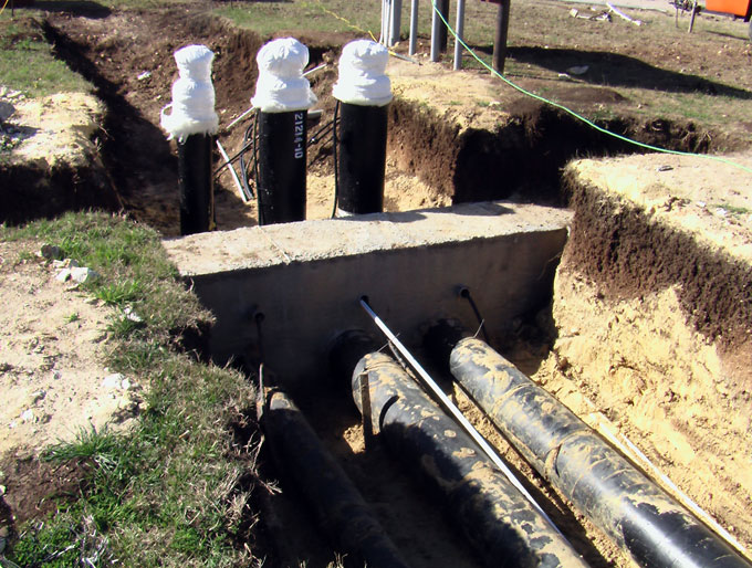
Pipes for district energy systems are pre-insulated with high-density polyurethane, mineral wool, or cellular glass.
Photo: Thermacor Process, L.P.A hot water district energy system always involves a piping loop. The supply and return pipes are installed side by side because at every branch pipe going off the supply pipe, a return line needs to feed back into the return pipe. By the time the main heating or cooling supply pipe reaches the last distribution point, its diameter has typically shrunk significantly because it’s carrying less water.
When a district energy system supplies both heating and cooling, four pipes are used: supply and return for both hot water and chilled water. Because a significant portion of the cost of a district energy system involves the trenching to lay pipes, it is wise to plan ahead and determine if a chilled-water loop is likely to be needed—and, if so, install it at the same time.
District energy systems use special pre-insulated piping. Most of the manufacturers are European, including the Danish companies Logstor A/S (www.logstor.com) and Star Pipe A/S (www.starpipe.com), and the Swedish company Powerpipe Systems AB (www.powerpipe.se). U.S. pre-insulated pipe manufacturers include Perma-Pipe of Niles, Illinois (www.permapipe.com) and Thermacor Process, L.P. of Fort Worth, Texas (www.thermacor.com). Most of the piping is steel that is insulated with polyurethane and then wrapped in a protective, high-density polyethylene (HDPE) jacket. A wide range of pipe diameters and configurations is available, including straight and curved sections, flexible pipe, double pipe (two pipes encased in the same insulated sheathing), and pipe sections fitted with built-in smaller-diameter branch pipes.
Determining the optimal pipe diameters is an important part of district energy system design. The amount of thermal energy delivered is a function of water temperature and flow volume, and a given flow volume can be achieved with fast-moving water in smaller pipes or at lower velocity in larger ones. Lowering the velocity reduces friction and therefore pumping energy, but larger pipes are more expensive to buy and bury. The required flow volume, the cost of pumping energy, and the cost of pipes determine what size pipes are used. Some pipes used in Europe are more than 30 inches (0.8 m) in diameter; the largest deliver hot water from remote power plants up to 30 miles (50 km) to urban areas. For smaller-diameter piping, especially branch connections into houses, pre-insulated flexible copper and cross-linked polyethylene (PEX) piping is also used. District energy pipes are often manufactured with embedded wires that are used to monitor for breaks and leaks.
Insulation is key to the success of district hot water systems. Two inches (5 cm) or more of high-density polyurethane (typically 4–6 lb/ft3, 65–90 kg/m3), mineral wool, or cellular glass insulation keeps heat loss from the pipes to a minimum—usually less than 2% per mile, sometimes a lot less. According to Pierce, the two miles (3 km) of pre-insulated steel piping at the University of Rochester’s district heating system—with pipes ranging in thickness from 3” (80 mm) to 16” (400 mm)—limits heat loss from the system to 0.5%. Some systems in Denmark, where hot water is piped as far as 30 miles (50 km), have less than 5% heat loss, according to Pierce.
Pipes are laid in well-drained trenches. Pipe joints and connections are made according to manufacturer recommendations (welding or soldering with metal pipe). Then the missing insulation around those connections is foamed in place or installed according to manufacturer specifications. Over this, the pipe joints are protected with sections of HDPE jacketing—often cylindrical jackets that fit over the pipe joints and are heat-shrunk in place. During this pipefitting, the continuity of monitoring wires (if provided) is maintained, and leads are connected to sophisticated alarm systems.
Using district energy
With most district heating systems, the hot water supply pipe enters the building from the hot water main and transfers heat to a central hot water tank, from which heating and water heating within the building are supplied.
Within this system is one or more meters (in North America, often called Btu meters) to measure how much heat from the district heating system the building is using. This key component allows the district energy utility to charge for energy use. The meters measure both incoming and outgoing water temperature and flow rate.
European manufacturers offer preplumbed modules that include the heat-exchange tank, all the valves and connections to the heat loads in the building, and meters. A single module replaces the individual boiler and water heater in a house. Indeed, European technology has advanced tremendously in recent decades, making it easy to use district heat.
If the temperature of the water being distributed is not high enough to satisfy heating loads, it can be boosted using small water-source heat pumps that use electricity to concentrate low-temperature heat. These are a common way of providing room-by-room thermal control in North American hotels and motels—the technology is well-developed, but the added cost and complexity is significant.
District cooling systems that deliver chilled water are used primarily in large commercial buildings, but a few new housing projects in Europe are utilizing such systems for air conditioning. As noted, in addition to distributing chilled water from a central source, it is also possible to cool a building with distributed
hot water using adsorption chillers, absorption chillers, or desiccant dehumidification. In either case, within the buildings, the cooling can be delivered via forced-air ducts or hydronic radiant cooling panels. If demand for air conditioning increases in Europe, due to either global warming or changing comfort standards, it will be interesting to see how these thermal needs are served by district energy systems.
Advancing District Energy Systems
For starters, in advancing district heating and cooling—and CHP plants to provide the thermal energy source—we should turn to northern Europe. District energy systems are used so widely in many countries that the knowledge base is tremendous; most of the mistakes have been made and the technology is fully mature. Described below are a number of strategies for advancing district energy and CHP in North America.Regional planning
Strong, coordinated regional planning is key to the success of district energy systems. Regional planning agencies can assist in this process; where such entities already exist, their scope can be broadened to specifically address district energy. For example, in master planning for a neighborhood, town, or region, provisions could be made for buried pipe corridors.
With residential development, planning could encourage the level of density needed for district energy systems to be viable—while also encouraging the protection of larger tracts of open space. According to Pierce, residential developments in northern Europe are being served by district energy systems even with a density as low as five or six homes to the acre (12–15 homes per hectare). Malcolm Lewis, P.E., Ph.D., of CTG Energetics, Inc., suggests that in the western U.S., where he does most of his work, a residential housing density of 20–25 units per acre (50–60 units per hectare) is needed, while the density could be lower in areas with larger heating loads.
District energy systems could be encouraged through tax incentives, development density bonuses (allowing more homes per acre, for example, when district heat is being used), lower permitting costs, and pollution discharge fees for heating equipment in buildings. District energy hookups could also be
required, much as municipal water and sewer hookups are required as part of the permitting process. Finally, the adoption of carbon taxes or higher energy taxes would also indirectly encourage use of district energy; indeed, higher energy taxes may be one reason district energy and CHP are more common in Europe than in the U.S.
Making buildings ready for district energy
Even if district energy systems are not available when new homes and commercial buildings are being planned and designed, various measures can facilitate easy conversion to district heating and cooling if and when they become available. In homes, this may involve locating mechanical heating and cooling equipment on the street side of the house, where piping lines would likely be brought in.The prospect of future district energy may also influence the systems for heat distribution within buildings. Houses with baseboard hydronic heat can easily be retrofitted for district heating simply by replacing the boiler with a heat-exchanger tank. Forced warm-air heating systems can also be adapted to district heat fairly easily. Electric heat, by contrast, is not adaptable to district heat.
With central air-conditioning systems in homes, if the evaporator and air handler are located in the same utility room as the boiler and water heater, retrofitting the system to make use of a chilled water supply should be relatively easy. Providing for easy access to all of the central equipment in a house will simplify later conversions.
Looking for synergies
If a district energy system is being considered in a community, synergies may improve the economics of the system. For example, suggests Pierce, consider burying fiber-optic cable with district energy pipes. Phone companies or cable television companies may be willing to share some of the cost of trenching for the opportunity to install cable in protected corridors. If municipal water or sewer lines are being upgraded, it might be possible to co-locate district energy supply and return pipes with the water and sewer lines.
Digging corridors for district energy piping may present opportunities to improve the landscaping treatments at the same time. Native vegetation could be planted, for example, and stormwater infiltration trenches could be provided in the same corridors.
LEED and district energy
The U.S. Green Building Council’s (USGBC) LEED® Rating System addresses district energy and CHP in several places. The new LEED for Neighborhood Development (LEED-ND) rating system that was released in a pilot draft in February 2007 includes a point for neighborhoods in which at least 80% of the total square footage is connected to a district energy system, and the system can meet at least 80% of the heating or cooling load. Additional constraints require minimum efficiency levels in the equipment and a limitation on pumping energy.LEED for New Construction (LEED-NC) does not specifically address district energy, but in October 2005 USGBC released a brief guidance document, “CHP Calculation Methodology for LEED-NC v2.2 EA Credit 1,” that outlines conditions under which buildings supplied by CHP district energy systems can take advantage of those systems’ efficiency gains in applying for points under LEED’s energy optimization credit. This document is available on the “LEED for New Construction” page of USGBC’s website.
Final Thoughts
There are many compelling environmental and economic reasons to embrace district energy systems far more actively than has been done recently in North America. District heating systems can eliminate the need for dirtier individual-building heating equipment, and they provide higher overall energy efficiency. When the energy source for a district heating system is a CHP plant, the benefits are even greater, because capturing and using a significant portion of the waste heat improves the efficiency of conventional power generation. And when the fuel source for CHP plants is a carbon-neutral, renewable energy source, district energy systems offer the best of all worlds.
While the benefits are obvious, the potential for less expensive district heat or chilled water should not in any way reduce the motivation to design and build highly efficient buildings.
For green designers, builders, planners, and developers, district energy systems and CHP offer important additions to our greening toolkits. Especially when coupled with renewable fuel sources, district energy and CHP can play a big role in reducing the carbon footprint of our buildings. To achieve greater market penetration, we should look to Europe for experience, and we should address these systems in architecture schools, LEED training programs, and continuing education programs of professional societies. It’s time we give district energy and CHP the attention they deserve.
For more information:
Morris Pierce, Ph.D.
University of Rochester
Rochester, New York
585-275-4331
mapi@mail.rochester.eduwww.energy.rochester.edu
International District Energy Association
Westborough, Massachusetts
508-366-9339
International Association for District Heating, District Cooling, and Combined Heat and Power
Brussels, Belgium
32 02 740 21 10
United States Combined Heat & Power Association
Bethesda, Maryland
301-320-2505
U.S. Environmental Protection Agency
Combined Heat and Power Partnership
U.S. Department of Energy
Distributed Energy Program
A Handbook on Low-Energy Buildings and District-Energy Systems by L. D. Danny Harvey, Earthscan Books, James & James Publishers, Ltd., 2006 ($275)
District Energy St. Paul
St. Paul, Minnesota
651-297-8955
Published March 6, 2007 Permalink Citation
Wilson, A. (2007, March 6). In the Pipeline: District Energy and Green Building. Retrieved from https://www.buildinggreen.com/feature/pipeline-district-energy-and-green-building
Comments
Wonderful and inspiring
Joseph Tembo
July 29, 2025 - 8:13 pm
Wonderful and inspiring article