Keeping the Heat Out: Cooling Load Avoidance Strategies
This article takes a detailed look at cooling load avoidance in residential and commercial buildings.
Cooling our homes and commercial buildings is becoming a more and more significant environmental concern. Both the total amount of energy we expend for cooling and the fraction of peak electricity use for cooling are on the rise. At the same time, our ability to reduce cooling loads in buildings is improving. We have new materials and technologies available to us, and we are improving our understanding of how buildings provide—or don’t provide—comfort.
For both economic and environmental reasons, it makes a great deal of sense to reduce our energy use for cooling. There are three ways to do this: keeping heat out of buildings (reducing cooling loads); expanding our comfort range (modifying work attire and providing air circulation, for example); and getting rid of heat once it gets in (heat rejection)—which can include both passive and active means. This article takes a detailed look at the first option: cooling load avoidance in residential and commercial buildings.
Energy Use for Cooling
Cooling accounts for about 15% of total U.S. electricity use. Approximately 64% of houses in the U.S. have mechanical air conditioning systems, according to the U.S. Department of Energy, and 37% have central air conditioning (1990). In hot climates, those percentages are far higher. These air conditioning systems consume 16% of residential electricity use at a cost of $11.3 billion dollars per year. Among new houses, some 77% are now built with central air conditioning. Mechanical cooling is required in virtually all commercial buildings and accounts for roughly 30% of electricity use.
Total electricity use for cooling tells only part of the story, though. Even more significant is the effect of cooling on peak utility electric demand. Buildings account for 43% of summer peak loads in the U.S., according to E Source, an energy and environmental research organization affiliated with the Rocky Mountain Institute. The impact of peak cooling loads can be dramatic. A 1°F increase in temperature on a hot summer afternoon in Los Angeles, for example, translates into a 300-megawatt increase in peak electric load.
The potential for reducing cooling loads—both peak and annual—is tremendous. In some northern parts of the country, cooling can be totally eliminated through careful attention to building design, with almost no sacrifice in comfort. Nationwide, E Source estimates that energy use for cooling can be reduced approximately 50% through cooling load reduction strategies.
Along with reducing operating energy use, cooling load reduction strategies can significantly cut up-front costs for equipment. The cost of air conditioning equipment is roughly proportional to size. Each additional ton of air conditioning capacity (12,000 Btu/hr. of cooling) costs about $1,000. (This is not the case at all with heating equipment: a 200,000 Btu/hr. furnace costs little more than a 100,000 Btu/hr. model.) Also, because air flow requirements for a cooling system are directly proportional to tonnage, downsizing the air conditioning equipment by half means the cross-sectional area of the ductwork can be cut in half, providing substantial savings in material and cost. The savings in mechanical system costs can often pay for the extra design and construction costs for measures that reduce cooling loads.
Finally, many of the strategies for reducing cooling loads have synergistic benefits, including savings in other energy end-uses, enhanced occupant comfort, and increased resale value of buildings.
Comfort and Cooling Processes
The ultimate goal of both heating and cooling buildings is to keep occupants comfortable. We produce heat internally through metabolic processes, and we gain and lose heat through our skin via conduction, convection, radiation, and evaporation. The rate of heat gain and heat loss from our bodies is influenced by activity level, clothing, and environmental conditions in the building: temperature, humidity, and air flow.
The relationship between temperature and humidity is particularly important in understanding comfort and strategies for reducing heat gain in buildings. A given volume of air contains both sensible heat and latent heat.
Sensible heat is the energy associated with temperature. It takes about 0.018 Btus to raise the temperature of dry air one degree Fahrenheit.
Latent heat is the energy locked up in the water vapor in a volume of air. Evaporating a pound of water takes about 1,050 Btus, and condensing that pound of water vapor releases 1,050 Btus. This is called the
latent heat of vaporization.
During the summer, high humidity levels are uncomfortable because they impede evaporation of heat from our skin. If a room is 78°F with a relative humidity of 50% we are likely to be comfortable, but if the relative humidity is 80%, we may feel too hot because our bodies can’t get rid of heat as easily. When outside air is introduced into a building, it contains sensible heat and latent heat, both of which contribute to the cooling load.
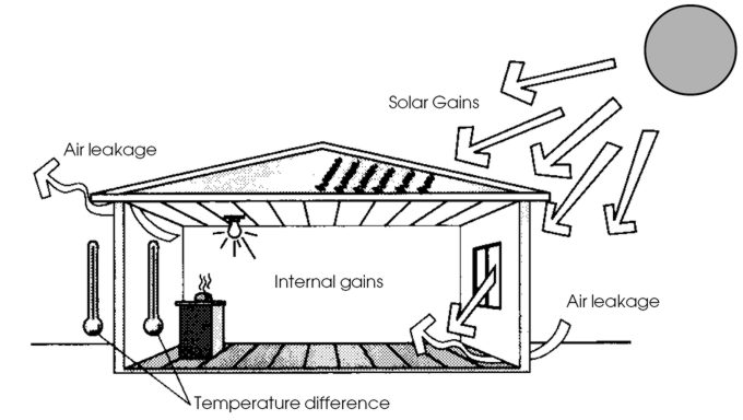
To understand how to reduce cooling loads in buildings, we need to understand where it comes from. There are four ways heat gets into buildings:
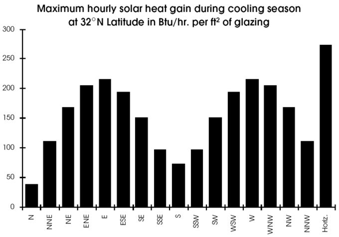
1. Solar heat gain.In energy-efficient houses, solar heat gain is usually the largest component of cooling loads, particularly in more northern climates, where it can account for up to 75% of the cooling load. Solar heat gain occurs through windows, glass doors, and skylights. It is also an important factor in the conductive heat gains discussed below. Solar gains involve sensible heat only. Solar gain is dependent on the incident angle at which sunlight strikes the glass. Thus it varies according to the orientation of the glass and the season. Figure 2 shows the maximum solar intensity during July on vertical glass at various orientations and on horizontal glass. Solar gain through east and west windows is much greater than that through south windows. An understanding of this principle is crucial to controlling cooling loads during the summer.
2. Conduction through the building envelope. Heat gain via conduction is proportional to the temperature difference across the building envelope (∆T). Because the outside air temperature in the summer isn’t that much greater than the indoor temperature in most of North America (∆T usually less than 25°F), conductive heat gain is usually relatively minor, particularly in energy-efficient buildings with good insulation levels. But in some situations, these gains can be significant. Sunlight shining on walls and roofs can boost outer surface temperatures as high as 140°F—which provides plenty of driving force for significant conductive heat gains. Conductive gains do not involve humidity; they involve sensible heat only.
3. Air infiltration and ventilation. Heat gain via air infiltration is dependent on the temperature difference across the envelope, outside wind conditions (and other factors that influence pressure differences across the building envelope), and the nature of intentional and unintentional openings in the envelope. Because outside air often has a high relative humidity, infiltration and ventilation introduce both latent and sensible heat gain. Air infiltration heat gain is much more significant in the south than in the north. In some situations, air with high moisture content (and latent heat) can be transferred from one part of a house, such as an attached greenhouse or basement, to another where the humidity causes discomfort.
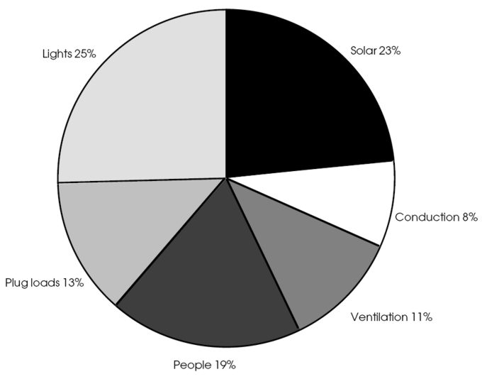
4. Internal gains. Internal gains are often the largest component of cooling loads in commercial buildings; in energy-efficient houses they may account for about 25% of the cooling load. Internal gains include heat given off by building occupants, electrical use within a building, hot water flowing through pipes, water vapor from cooking and bathing. Virtually all electricity use in a building is ultimately converted into heat at a rate of 3,413 Btu/kWh. Internal gains can include both sensible and latent components. In homes, latent heat gains can be significant. Each pound of water vapor introduced contributes a latent heat gain of 1050 Btu.
Reducing Cooling Loads
Through careful attention to building design, material selection, landscaping, and building management, it is usually possible to reduce cooling loads by 50% compared to conventional buildings. In some parts of North America, cooling loads can be eliminated altogether. Recommended strategies for reducing cooling loads are summarized below and described in detail in the checklists at the end of the article.
In residential buildings, the greatest attention should usually be focused on reducing solar gains. Careful building orientation, providing vegetative shade, minimizing window area on the east and west, careful selection of glazings, and shading windows with architectural features or window treatments to reduce gain are the most important strategies. In commercial buildings, use of low-solar-gain glazings is the most important strategy for reducing solar gain.
Internal gains are by far the most significant cooling load in commercial buildings, and they are usually second most important in houses. Strategies for reducing these gains include installation of energy-efficient electrical equipment, insulation of cooling system ducts, insulation of hot water tank and pipes in the occupied space, spot ventilation of concentrated heat sources, and elimination or reduction of water vapor sources.
Conductive and infiltration heat gains should be fairly minor in energy-efficient buildings that are managed carefully. Conductive heat gain can be controlled through insulation, radiant barriers, reflective roof and wall surfaces, and good attic or roof ventilation. Infiltration gains can be minimized through airtight construction, careful management of windows and whole-house ventilation by building occupants, and isolation of humidity sources from occupied spaces.
Simple strategies to reduce summer heat gain are among the most significant environmental building practices. Many cooling load avoidance strategies are inexpensive, though they do require an investment in design. Extra design costs can often be recovered through downsizing of mechanical cooling and air distribution systems. Savings in operating costs are often synergistic: more efficient lighting, for example, costs less to operate and also reduces air conditioning loads.
While cooling load reduction is extremely important, it is only part of the solution in most parts of the country. Remaining cooling loads must be satisfied through a combination of expanding the comfort range of building occupants and implementing cooling strategies (both natural and mechanical). Here, too, there is room for great improvement from conventional practice.
Van Nostrand Reinhold Company, New York, 1986, 312 pages.
This is the best book available on cooling load avoidance and low-energy cooling strategies. It is out-of-print, but copies are available for sale directly from the author.
Clear, well-illustrated booklet on residential cooling strategies, including load avoidance.
Available from Saturn Resource Management
324 Fuller Avenue., S-8
Helena, MT 59601
406-443-3433; 406-442-1316 (fax)
Florida Solar Energy Center
300 State Road 401
Cape Canaveral, FL 32920
407-783-0300; 407-783-2571
The leading research center on cooling issues, especially those appropriate to a hot, humid climate. FSEC has a wide range of reports and fact sheets available.
The energy used for space heating and cooling in residential buildings produces 420 million tons of carbon dioxide per year and 8.9 million tons of atmospheric pollutants.
Cellulose Insulation: An In-Depth Look at the Pros and Cons
Should we be recommending cellulose to our clients? If so, on what basis? If not, why—what are its drawbacks?
Cellulose insulation has been the darling of the green building movement because of its recycled content, low embodied energy, low-tech processing, and excellent energy conservation performance. But concerns are also raised about health risks for cellulose installers and occupants of cellulose-insulated buildings. In fact, some healthy home advocates strongly discourage its use. Should we be recommending cellulose to our clients? If so, on what basis? If not, why—what are its drawbacks? EBN took an in-depth look at these questions, and we report here on our findings.
Manufacturing
Cellulose insulation is a fairly simple material produced from one of our biggest solid-waste products: newspaper. The 70 to 80 cellulose insulation manufacturers in North America purchase old newspaper that has been collected through recycling programs. There are two stages of production, according to Doug Leuthold of Advanced Fiber Technology, a company that makes cellulose insulation manufacturing equipment. In the first, the newspaper is chopped into pieces from one to several inches in diameter. The second stage (finishing mill) differs considerably from one manufacturer to another. The oldest and most common finishing mill is a hammer mill in which swinging metal plates attached to a rotating shaft beat the newspaper in a chamber until the pieces are small enough to fall through a screen. The maximum size of cellulose particles produced in the hammer mill is typically 3⁄8” to 1⁄4”. Disk refiners are a little different; the chopped newspaper is shredded as it falls between two rotating plates. A third, newer, process is known as fiberization. Instead of cutting the paper, fiberization actually disaggregates it back into individual fibers. In the fiberization process developed by AFT, high-pressure air is used to “blow particles apart,” says Leuthold. “You end up with a fluffy product that looks like the padding in disposable diapers, except that it’s gray.” Fiberization produces lower-density cellulose with a number of advantages.
Once the newspaper has been adequately shredded, chemicals are added to provide fire-retarding and mold-inhibiting properties to the insulation. The most common chemicals used today are boric acid, sodium borate (borax), and ammonium sulfate. Boric acid and sodium borate have the advantage of not only providing fire retardancy, but also adding mold, insect, and rodent resistance to the insulation. Aluminum sulfate has been used in the past as a fire retardant, but is rarely if ever used today, according to Daniel Lea of the Cellulose Insulation Manufacturers Association, or CIMA. Most manufacturers use a mixture of borates and ammonium sulfate, and some add small quantities of several phosphates. According to Dave Yarbrough at Oak Ridge National Laboratory, there is a trend in the industry to replace some of the borate with ammonium sulfate, because the latter is less expensive. After the insulation is mixed with fire-retardant chemicals—and in some products dry binders—it is bagged and shipped to building supply outlets or installers.
There are a number of ways to install cellulose insulation. The oldest and simplest use is loose-fill cellulose in attics. The insulation is blown or poured into the attic space where it provides about R-3.7 per inch. Dry-blown cellulose is also installed in walls as a retrofit insulation material. Holes are typically drilled through the exterior sheathing after removing several sections of siding, and the cellulose is blown in.
Wet-spray cellulose, as the name implies, has water added during installation to make it stick when blown into wall cavities (binders are sometimes used as well). Conventional wet-spray cellulose using a hammermill product is usually installed quite wet—sometimes with more than 100% water on a “dry-weight” basis (weight of water divided by weight of dry cellulose), or about four gallons of water per 30-pound bag. By using fiberized cellulose instead of hammermill cellulose, the water content can be significantly reduced. American Environmental Products (AEP), a Virginia cellulose manufacturer, has gotten the moisture content down to about 28% (dry-weight basis), according to Ivan Sandau of AEP. The company offers cellulose either with or without a dry binder. The binder, described as an organic product approved as an agricultural food additive, is activated upon contact with water.
Another relatively new formulation of cellulose insulation, referred to as
stabilized cellulose, is used in attics. This product has a binder in it and is applied with a small quantity of water. The binder prevents settling, which may otherwise reduce the installed thickness of loose-fill cellulose insulation by as much as 25%. American Environmental Products, one of several manufacturers producing stabilized cellulose, achieves a 1.3 lb./ft3 density with its stabilized attic insulation.
Two other approaches used for walls do not require water. In the dense-pack process, cellulose is blown into closed wall cavities at a relatively high density of 3 to 31⁄2 lbs./ft3. Because of the high density, settling does not occur. With the other approach, installers use forms to blow dry cellulose into open wall cavities. The forms, which are propped against the inner side of stud bays, hold the insulation in place as it is installed, and the insulation stays in place after forms are removed and until the inner wall surface is installed.
A Market for Recycled Newspaper
North America produces roughly 13 million tons of newspaper each year—about 100 pounds per person. Fifty-five percent of this is currently recycled (1992) according to the American Forest and Paper Association; the rest accounts for about 4.6% of municipal solid waste. While these statistics are a big improvement over ten years ago when newspaper accounted for 8% of our municipal solid waste, we still landfill or incinerate a huge amount.
There are various ways old newspaper can be recycled. The biggest use, turning it back into new newspaper, requires significant processing (de-inking and bleaching, for example), which takes a lot of energy and produces contaminated water that must be treated. Recycling old newspaper into cellulose insulation is much simpler: de-inking is not required, there is no pollution generated in the process, and very little energy is used.
According to CIMA, 414,000 tons of cellulose insulation were produced in 1990. Because the finished product is approximately 80% recycled newspaper by weight, this means that cellulose insulation currently provides a use for roughly 330,000 tons of old newspaper. This represents 4.6% of total recycled newspaper (see pie chart). On a volume basis, EBN estimates that cellulose currently has about 10% of the fiber insulation market (fiberglass, mineral wool, cellulose). Increasing the market share of cellulose insulation—and thus increasing the use of recycled newspaper—will further strengthen markets for recycled newspaper, which will improve the economic viability of recycling programs. (Today, municipalities often have to pay to get rid of the newspaper they collect through recycling because the markets for recycled newspaper are so weak.)
While the primary ingredient in cellulose insulation is in bountiful supply, the second-most-used ingredient may not be. In North America, borax crude was first mined in Death Valley, California, in 1883, using 20-mule-team wagons (made famous by the television program "Death Valley Days"). A far larger borate ore deposit was discovered in 1925 in the Mojave Desert near Boron, California, and production today is about 10,000 tons per day from an open-pit mine. Since then, no additional borate reserves have been discovered. A source in the company estimated that reserves will last only about 50 years at today’s consumption level. U.S. Borax currently accounts for about 50% of world borax production; the only other major source is in Turkey.
Low Embodied Energy
Because cellulose insulation production is such a simple, low-tech process, manufacturing plants can be small and widely scattered. That means transportation energy can be kept low. By contrast, fiberglass manufacturing is far more complex and requires heavy capitalization and centralized production (i.e., longer shipping distance).
Comparing the Embodied Energy of Cellulose and
Other Insulation Materials
Embodied energy figures (other than cellulose) from a 1991 study by Franklin Associates for the Society of the Plastics Industry
The only estimates of embodied energy in cellulose insulation EBN found were from Canadian manufacturer Therm-O-Comfort Co., Ltd. In a 1991 letter to the Canadian Standard Association, Therm-O-Comfort estimated primary energy consumption for cellulose insulation to be 85 kWh/ton (145 Btu/lb.). This figure does not account for the fire-retardant chemicals or transportation energy. Relative to most industrial processes, borax mining and refining is a “low-energy” process. Even with a conservative (high) estimate for fire retardants, embodied energy for cellulose insulation would be only about 750 Btu/lb. This figure is less than one-seventh the energy used to produce fiberglass, and one-30th that required for polystyrene (see table).
In addition to the environmental benefits relating to resource use and embodied energy, cellulose insulation also has performance advantages over most other fiber insulation materials. Cellulose insulation has a higher R-value than standard fiberglass insulation, though high-density fiberglass can provide higher R-value than cellulose. With attic applications, loose-fill cellulose also blocks air convection within the insulation—a process that can significantly reduce the effective R-value of loose-fill fiberglass in very cold regions (see below). Settling, however, is more of a concern with loose-fill (non-stabilized) cellulose than with fiberglass insulation. In wall applications, wet-spray cellulose fills around wires and pipes, sealing the cavity more effectively than fiberglass batts, and settling does not occur. In fact, because of the very good air barrier provided by wet-spray cellulose, many installers suggest that a polyethylene vapor barrier is not required.
Unlike with fiberglass, the R-value of cellulose insulation does not increase as the density increases. Loose-fill cellulose in attics, at a typical density of about 1.5 lbs./ft3 insulates to between 3.6 and 3.8 per inch according to Dave Yarbrough at Oak Ridge National Laboratory. At higher densities, such as wet-spray wall applications (typically 2-3 lbs./ft3), the R-value is slightly lower: 3.5 to 3.6 per inch. With fiberglass, the R-value increases at higher densities up to about R-4 per inch.
In side-by-side tests conducted at the University of Colorado School of Architecture and Planning, two identical test buildings were built on insulated platforms. Cellulose insulation increased the air tightness by 74% over the uninsulated building, while the fiberglass insulation increased air tightness by 41% (neither building had a vapor barrier). The heating tests showed that the cellulose-insulated building used 26% less energy than the fiberglass-insulated building. Because these were short-term tests, it is not known whether settling of the loose-fill cellulose insulation over time would affect its energy performance.
Comparisons between loose-fill cellulose and loose-fill fiberglass attic insulation in very cold conditions have also been made both by the University of Illinois and by Oak Ridge National Laboratory. Both studies showed that at very cold temperatures loose-fill fiberglass loses up to 50% of its R-value, while loose-fill cellulose and fiberglass batt insulation do not. It is worth noting, however, that the extra heating costs from convection in loose-fill fiberglass in even an extreme North Dakota climate will only increase annual heating costs by about 2.4¢/ft2 of attic at an R-19 insulation level and 1.4¢/ft2 at an R-38 insulation level.
Health Concerns
Just how safe cellulose insulation is for installers and homeowners has been the subject of considerable controversy in the past few years. Some healthy house proponents argue that the chemicals found in the insulation and the cellulose fibers themselves are harmful and potentially even carcinogenic. Let’s take a look at these chemicals.
Cellulose insulation is typically about 20% fire-retardant chemicals by weight. The most commonly used fire retardants in cellulose insulation are boric acid, sodium borate, and ammonium sulfate. Informational materials published by Owens Corning Fiberglas claims that borates and boric acid are “known to cause reproductive disorders in rats. Medical authorities also warn that borates and boric acid may cause toxic poisoning in humans if absorbed through a cut or scrape. Ingesting as little as 1/8 ounce of these chemicals can be fatal to infants.” An article in the British Journal of Industrial Medicine (February 1993) by J. M. G. Davis goes into greater detail about health concerns:
“Boric acid itself is a toxic material and can be lethal to humans when ingested in gram quantities. It is not considered that the inhalation of cellulose insulation dust could approach this lethal toxicity but the heavily impregnated respirable cellulose dust will liberate the readily soluble boric acid in significant amounts in lung tissue. Symptoms of sublethal toxicity to boric acid include abdominal pain, liver, kidney, and lung dysfunction and severe exfoliative dermatitis.”
A front-page article in
Energy Design Update (June 1993), however, brings into question the validity of Davis’s article by noting that he is “under retainer to fiberglass and rockwool manufacturers and that in fact ‘one of those groups’ suggested he write the journal article.” A letter from Davis is quoted in the article as follows: “I would certainly emphasize that I do not feel that most cellulose fiber manufacturing or products present any hazard at all, if only because most will not liberate respirable fibers in significant amounts. Even in the most questionable case of shredded paper insulation materials, where the chemicals I listed [boron fire retardants] do occur, I fully acknowledge that there is no definite evidence that sufficient [amounts] can be inhaled to be harmful” (bracketed items from EDU article).
Concerns have also been raised about ink residues in cellulose insulation. There are two basic types of ink used in newspaper printing, according to Don Hensel, Environmental Manager at the Newspaper Association of America (NAA). Black inks have traditionally been a mixture of 60-80% petroleum-based mineral oil, 15-20% pure carbon black, and small amounts of other additives. In recent years, soy-based inks have gained in popularity. With these inks, oil made from soy beans replaces the mineral oil; the carbon black is still the same. The primary concern with inks has always been colored inks, which were traditionally made with toxic heavy metals such as cadmium and lead. According to Patricia Penza of the General Printing Ink Division of Sun Chemical, however, colored pigments weren’t used in the news industry until about ten years ago. By that time, she said, the health hazards of lead and other heavy metals were well known and NAA (then the American Newspaper Publishers Association) banned their use in newspaper inks.
Dr. John Comerford at the College of Agricultural Sciences at Penn State University has studied the safety of using shredded newspaper as animal bedding. He found no detectable levels of 16 different hydrocarbons in blood and liver samples. Of the metals cadmium, copper, lead, and mercury, only copper was found in measurable levels. Copper levels were “well below the toxic level” and higher levels were found in a control group of cattle that were bedded on sawdust. As for the newspaper bedding itself (shredded newspaper), cadmium, copper, and lead were found at levels less than 1⁄100 the levels permitted in feed.
Insulation expert David Yarbrough of Oak Ridge National Laboratory dismisses most of the concern surrounding toxicity of cellulose. “I think that’s a major red herring,” he said. “The installer in an attic certainly is exposed to quite a bit of dust, …[but] as far as occupants are concerned, to me it’s a nonsense issue.” He noted that these health concerns were originally prompted by asbestos and that the concerns bled over into mineral fibers. The mineral insulation industry, “in a logical counter argument, said you ought to look at the cellulostic fibers and the chemicals and dust and all that’s associated with it,” added Yarbrough.
EBN’s recommendations on the health concerns raised with cellulose are as follows: 1) don’t eat it, 2) installers should always wear proper respiratory protection, and 3) as with other fiber insulation materials, it should be installed with a continuous air-tight barrier between the insulation and the living area (i.e., in most of the country, that means installation of polyethylene vapor barriers on walls and ceilings).
Potential combustibility of cellulose insulation has long been an issue of concern, given the inherent combustibility of its primary raw material. As mentioned, various chemicals are added to provide fire-retardant properties. The biggest concern with these chemicals—all of which are readily water-soluble—is that they might leach out or somehow dissipate from the insulation over time. Concern has been particularly great with borates.
The North American Insulation Manufacturers Association (NAIMA), a trade association representing the fiberglass and mineral wool industries, has publicized the results of several reports showing that the fire resistance of cellulose insulation drops over time. Specifically, NAIMA cites a study by an association member of 24 loose-fill cellulose insulation samples from attics in six states that had been in place for at least two years. “Of the 19 samples tested for critical radiant flux [a value that influences the ability of flame to spread across insulation], 10 failed to meet the ASTM C 739 criterion.” Even more damaging is an ongoing study by the California Bureau of Home Furnishings and Thermal Insulation (CBHF) to measure the long-term performance of cellulose insulation relative to flammability. Over three years of testing, boric acid and borax levels were found to drop and the insulation samples “failed to meet the critical radiant flux requirements of ASTM C 739,” according to the NAIMA report.
The CBHF does not seem overly concerned about these results, however. In an October 1992 letter to a cellulose insulation manufacturer (provided to EBN by CIMA), the chief of the CBHF said that “…the long term aging studies show the samples maintain their ability to pass the smoldering test normally administered on new materials. We consider the smoldering test a much more important test than the critical radiant panel in predicting in-field fire performance…. We have not received a significant number of reports from California fire departments indicating that insulation materials constitute a fire hazard or major consequence.”
Several studies by researchers at Tennessee Technological University (TTU) and Allied Signal Corporation provide evidence that the fire-retardant chemicals do not disappear from cellulose insulation except at much higher temperatures than would commonly be found in attics. The most thorough and widely quoted study was done by David Yarbrough of ORNL and N. Chiou of TTU and published in
Energy and Buildings in 1990. Enough vibration to simulate 672 years of use in an attic was found to cause no measurable settling of boric acid or borax in test samples. As for evaporation (sublimation) of boric acid from cellulose, the study found that at very high temperatures (90°C or 194°F) and 100% relative humidity, the loss of boric acid was significant, but the loss was negligible when the temperature is lower 70°C (158°F), even at 100% humidity and air exchange rates of 2.0 attic changes per hour. “It appears that it would take 300 years or more at 70°C, 100% relative humidity, and air exchange rates from 1.0 to 2.0 attic volumes per hour to lose enough boric acid to significantly affect the combustion tests,” according to the article’s authors. Separate studies of ammonium sulfate by David Yarbrough and Allied Signal Corporation reached similar conclusions: that loss was not significant except at very high temperatures.
EBN considers the potential loss of fire-retardant chemicals to be the most significant concern relating to cellulose insulation. Further research on this concern is clearly needed, but the apparent lack of building fires in which cellulose insulation has been implicated gives us confidence that cellulose insulation is safe enough for use.
Disposal of Cellulose Insulation
When the useful life of any insulation material comes to an end—i.e., when the building is demolished or the insulation removed during renovation—what happens to it? Cellulose is not readily reusable as an insulation material. Even if it weren’t so messy, given the concerns about fire-retardant chemicals with new cellulose insulation, the acceptability of fire retardants in old cellulose should be highly suspect. In most cases, the material is either landfilled or incinerated. If landfilling is the disposal method, cellulose insulation does pretty well because of its inherent biodegradability. As the cellulose decomposes, however, the borate and ammonium sulfate fire-retardant chemicals will remain. In older landfills, these water-soluble chemicals, dissolved in rainwater (leachate), can permeate through the underlying soils. According to a Material Safety Data Sheet from U.S. Borax, “although boron is an essential micronutrient for healthy growth of plants, it can be harmful to boron-sensitive plants in higher levels,” and it is toxic to some fish at levels of 1 mg per liter. Overall, the toxicity of the borates in cellulose insulation is low enough that cellulose insulation is not considered a hazardous material even in California, which has the nation’s most stringent standards. “You can dispose of it in any landfill,” according to Jerry Pepper, manager of environmental affairs at U.S. Borax.
If ammonium sulfate gets wet or thermally decomposes, it can produce sulfuric acid, which is corrosive to metals. There have been anecdotal reports of copper pipes and steel truss fasteners in attics corroding when in contact with cellulose insulation that has gotten wet. With the rising popularity of wet-spray cellulose for wall applications, the issue of corrosivity is particularly significant. Many wet-spray cellulose installers specify material treated only with boric acid and borax to eliminate concern about corrosion. According to David Yarbrough, however, all cellulose insulation must pass corrosivity tests, and if properly installed, any commercially available cellulose should be all right. To improve resistance to corrosion, some manufacturers may add corrosion inhibitors.
Does Wet-Spray Cellulose Insulation Dry Out?
With wet-spray cellulose insulation concern is often expressed that moisture from the insulation might remain trapped in the wall cavity and result in rotting or mildew growth. The concern is greatest in situations where there is an effective vapor barrier on both sides of the wall cavity—for example, when foam sheathing or plywood is used on the exterior and a polyethylene vapor barrier is used on the interior. There have been a number of horror stories, such as a public housing project in New England where in one building, even after 11⁄2 years, the insulation moisture content was found to be 30-60% (Energy Design Update, July 1989). In this case, it appears that the insulation was installed very wet (up to 200% moisture on a dry-weight basis—five to six gallons of water per 30-pound bag), and the wall system impeded drying (interior polyethylene vapor barrier and meticulously installed extruded polystyrene on the exterior). An experimental study of different wall systems by the Canada Mortgage and Housing Corporation in Newfoundland (1986 and 1987) found that even after two years, wet-spray cellulose had not dried and the moisture level in studs was about 60% (Energy Design Update, November 1987).
A study in Calgary, Alberta, on the other hand (where the climate is drier), showed that wet-spray cellulose dries out quite well. One wall of a test house was configured to test for the effect of poly vapor barriers and the tightness of the exterior sheathing. Even the wall section with a poly vapor barrier on the interior and well-sealed plywood sheathing on the exterior dried to acceptably low moisture levels within 120 days (Energy Design Update, October 1989).
Clearly there is cause for concern in humid climates. Wet-spray cellulose should only be used in situations where adequate provision has been made for drying of the insulation. Joe Lstiburek, of Building Science Corporation, who co-authored the
Moisture Control Handbook for the U.S. Department of Energy, says that when using wet-spray cellulose the wall must have adequate drying potential. In northern climates, it must be able to dry to the exterior. That means a moisture-permeable exterior sheathing such as one-by lumber, asphalt-impregnated fiberboard, or an exterior gypsum board. In warm climates where there will be central air conditioners operating during the summer, the wall can be designed to dry to the interior by leaving out the interior vapor barrier, says Lstiburek.
If vapor retarders are to be used on both sides of wet-spray insulation, provision needs to be made for the insulation to dry out before the wall system is closed in. Depending on the climate conditions, low-water-content wet-spray cellulose insulation can dry at a rate of up to about one inch of depth per day, according to Ivan Sandau of American Environmental Products.
Along with allowing wet-spray insulation to dry, keeping it dry is also very important. Cellulose can absorb moisture. If soaked, it can compress. Even if only moistened, its R-value will drop, reducing energy performance, and the resultant humidity can permit mold growth or rotting of wood framing members. Proper detailing to prevent migration of water or water vapor into the insulation—from either the inside or outside—should be followed.
Cellulose insulation is receiving a big image boost from Louisiana-Pacific on two accounts. First, L-P is the first company to market cellulose insulation nationally; its Nature Guard™ product is produced at four plants around the country and actively promoted through advertising campaigns and at trade shows. Second, at the end of July, L-P launched a program to guarantee low heating bills for homes insulated with their cellulose. Under the Snug Home program, a home must be tested for air tightness, and the leakage ratio must be between 2 and 3 (leakage ratio is defined as the Effective Leakage Area, divided by the square footage of the building envelope, divided by 100). If the home meets the air tightness requirement, L-P reviews the plans and determines the expected heating load, adds in a comfort margin, and provides a written warranty listing the maximum yearly heating costs for a period of three years. L-P will pay any difference in heating cost. While this program only covers Nature Guard, publicity about the program will increase awareness of cellulose insulation across the board, helping out all producers.
The Bottom Line
After thorough review, we at EBN have concluded that properly installed cellulose insulation is acceptable from a health standpoint. We found no significant risk of indoor air quality problems, combustion, or moisture damage if appropriate installation procedures are followed. The most significant concern—apparent loss of certain fire-retardant properties—calls for additional research but does not appear so significant as to suggest a moratorium on use. Given its environmental advantages over most other insulation materials (low energy production, high recycled material content, and biodegradability), EBN believes that cellulose insulation should be a preferred insulation material for environmentally concerned builders and designers. This is not to say that cellulose is the perfect insulation material; it is not. Care must be taken in its use to ensure proper performance and a long, safe operating life. A checklist for cellulose installation follows.
Embodied Energy--Just What Is It and Why Do We Care?
Almost all the attention paid to energy conservation in buildings has focused on reducing their operating energy, but embodied energy can add up to many years’ worth of operating energy in an efficient building.
Estimates provided by Professor Ray Cole of the University of British Columbia’s School of Architecture. House modeled is a 3,750 ft2 ranch. Energy-efficient version assumes ceiling R-values raised from R-24 to R-42, 2x4 walls replaced with 2x6 walls, additional glazing on south elevation, and added thermal mass to temper indoor temperatures.
Almost all the attention paid to energy conservation in buildings has focused on reducing their operating energy. Given the energy hogs that many buildings were (and are), this focus is appropriate. As builders and architects succeed in making their buildings more efficient, however, the energy used to build buildings starts to look significant. This embodied energy can add up to many years’ worth of operating energy in an efficient building (see table). While taking steps to reduce operating energy is clearly the first priority, it makes sense to look for options that minimize the initial energy investment—the embodied energy—as well.
Embodied energy is a term coined to express the energy consumed in the production of a particular product or material. Some scientists use the term energy intensity to describe the embodied energy per unit (pound, kilogram, cubic foot, cubic meter, etc.) of a material. The energy used to produce the materials, together with the energy needed to assemble them, gives the embodied energy of a building component, or of a whole building. Energy intensity figures for materials, or embodied energy values for components, can provide useful information for comparing different building products, or choosing from among several different materials.
Quantifying the energy intensity of materials is not an exact science. Manufacturing procedures can vary greatly from one site to the next, or by season. Every effort to measure energy inputs requires many assumptions, and these often vary greatly among researchers. Production generally begins with one or more raw materials that have to be mined or harvested, transported to factories, and processed into usable products. The finished products then have to be transported to the building site. For some materials the processing and manufacturing stage can have several steps, with initial processing at one site, further transportation and secondary processing at another site, and so on. The flow of materials and energy for products made up of many different components (such as a window, for example) can be quite complicated.
Some researchers have worked to clarify the assumptions involved by assigning different levels or orders of energy use based on how directly the activity is connected to the manufacturing process:
First order energy: fuel use for mining, transporting raw material, energy use at manufacturing facility.
Second order: energy used to produce the equipment and machinery that does the work, and to transport workers to and from the site.
Third order: general support services and social services for workers, second order energy for machinery, equipment and infrastructure.
While some embodied energy studies have attempted to include second and third order energy values in their data, most do not. These secondary energy values can be quite large taken as a whole, but once their contribution to the energy picture is spread over the full amount of material it becomes much less significant. The amount of diesel fuel burned by an excavator in a gravel quarry (first order energy), will over its useful life dwarf the energy invested in making the machine (second order energy). Other second order contributions, such as the transportation of workers, can be more significant because they occur on an ongoing basis along with the actual mining or manufacturing. The unknowns and variability from one site to the next make these figures almost impossible to quantify, however. As a result, many researchers choose to assume that such factors will be comparable from one industry to the next, and as such can be left out without compromising the relative embodied energy assessment.
The most important and difficult part of relative embodied energy assessments is making sure that all the assumptions and boundaries of the study are the same for all materials involved. When comparative work is done by one researcher or group of researchers the parameters can be established and shared. To date, however, most embodied energy research projects have focused on one particular field or industry, and comparing the results of different projects is tricky at best.
Industry associations representing wood products, plastics, and concrete have all commissioned studies in the hopes of showing the energy advantages of their materials. As might be expected, the conclusions released from those studies that have been completed vary tremendously. A study commissioned by the Society for the Plastics Industry (SPI) and performed in 1990 by Franklin Associates of Kansas City, Missouri, provides embodied energy values for cement that are three to five times higher than those suggested by independent Canadian studies from the mid-eighties. Research done by Scientific Certification Systems of Oakland, California, for the Western Wood Products Association has not been released to the public, while the concrete studies are just beginning. Until several different associations commission studies from the same researcher, using the same methods, it is impossible to compare the results reliably.
Fortunately, there is some independent research to work from, including efforts to incorporate embodied energy into the larger environmental picture. While much of the current work is from Canada and Europe, it is American researchers in the mid-1970s who laid the groundwork in terms of energy analyses of industrial processes. The work of Harry Brown (on industrial processes in general), and Richard Stein and Diane Serber (on energy use in building construction), provided the raw data which is still used as a basis for many studies. By comparing this research with industry-funded studies it is possible to make some reasonable comparisons of materials, at least those that have been studied. As more material becomes available, EBN will keep you updated on the results of those comparisons.
Sidebar
What Embodied Energy Doesn’t Tell UsEmbodied energy values can play an important role in assessing the overall environmental impact of a material, but they cannot give the whole picture. Among the other important factors to consider are:...
Brown, Harry, et al. 1985 Energy Analysis of 108 Industrial Processes. Washington, D.C.: U.S. Department of Energy.
Cole, Raymond J. and David Rousseau (both of the Environmental Research Group, School of Architecture, University of British Columbia, Vancouver, BC, Canada, V6T 1W5). “Environmental Auditing for Building Construction: Energy and Air Pollution Indices for Building Materials.” Building and Environment Vol. 27, No. 1, pp. 23-30, 1992.
Corrim Panel II. “Wood for Structural and Architectural Purposes,” Wood and Fiber Vol. 8, No. 1 Spring, 1976.
Food and Agriculture Organization of the United Nations. Energy Conservation in the Mechanical Forest Industries. Rome, Italy. 1990.
Franklin Associates, Ltd. 1991. Comparative Energy Evaluation of Plastic Products and Their Alternatives for the Building and Construction and Transportation Industries. Prairie Village, Kansas. Report prepared for The Society of the Plastics Industry.
Hannon, Bruce et al. “Energy and Labor in the Construction Sector.” Science Vol. 202, 24 November 1978, pp 837-847.
Stein, R.G. and Diane Serber. 1979. “Energy Required for Building Construction.” Chapter 10 of Energy Conservation Through Building Design. D. Watson. New York, McGraw Hill.
Other Contacts:
Scientific Certification Systems, 1611 Telegraph Ave., Suite 1111, Oakland, CA 94612; 510/832-1415.
Canadian Mortgage and Housing Corporation, 682 Montreal Rd., Ottawa, ON K1A 0P7, Canada; 613/748-2367. CMHC is developing an extensive database program, called Optimize, to assess the environmental impact of houses. Optimize runs on Excel and requires an IBM or compatible PC with high-speed processor. It is currently in final testing stages.
 1. Solar heat gain. In energy-efficient houses, solar heat gain is usually the largest component of cooling loads, particularly in more northern climates, where it can account for up to 75% of the cooling load. Solar heat gain occurs through windows, glass doors, and skylights. It is also an important factor in the conductive heat gains discussed below. Solar gains involve sensible heat only. Solar gain is dependent on the incident angle at which sunlight strikes the glass. Thus it varies according to the orientation of the glass and the season. Figure 2 shows the maximum solar intensity during July on vertical glass at various orientations and on horizontal glass. Solar gain through east and west windows is much greater than that through south windows. An understanding of this principle is crucial to controlling cooling loads during the summer.
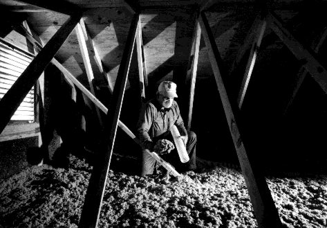 There are a number of ways to install cellulose insulation. The oldest and simplest use is loose-fill cellulose in attics. The insulation is blown or poured into the attic space where it provides about R-3.7 per inch. Dry-blown cellulose is also installed in walls as a retrofit insulation material. Holes are typically drilled through the exterior sheathing after removing several sections of siding, and the cellulose is blown in.
 North America produces roughly 13 million tons of newspaper each year—about 100 pounds per person. Fifty-five percent of this is currently recycled (1992) according to the American Forest and Paper Association; the rest accounts for about 4.6% of municipal solid waste. While these statistics are a big improvement over ten years ago when newspaper accounted for 8% of our municipal solid waste, we still landfill or incinerate a huge amount.